Travis McVoy

Wind Tunnel
DISCLAIMER: This project was done independently of academic supervision. Everything below is therefore addressed to the layperson and SHOULD NOT BE REFERENCED IN FORMAL LITERATURE.
Note: The photos are slides. If you hover your mouse on them, you can click through and view other photos.
Motivation
I attended a community college (Foothill) prior to pursuing a degree. In my calculus class I became friends with Daniel, who expressed interest in aerospace engineering. He was frustrated that he didn't have the resources to gain experience in aerospace engineering before he transferred to a 4-year institution.
When classes went online in 2020, I convinced Daniel to quarantine and move in with me. I had the workspace and tools necessary to build a wind tunnel and I knew he had the knowledge.
One might ask, "What did I have to gain in all this?" I suppose you could argue that I would have much more fun working on an interesting project with a friend than I would taking classes online, but that's not why I took on the project. In the past, I've been told my academic goals are too ambitious and that I will fail. Daniel wanted to learn German and study at the Technical University of Munich (TUM), which is, as I understand it, regarded as one of the best engineering schools in Germany. Studying at TUM would give Daniel better chances at gaining an opportunity to work on F1 car design, which is his dream. The moment for me to realize my dream had sort of already passed. Daniel still had time, and I thought that if we built a wind tunnel together, it might strengthen his application to TUM.
Wind Tunnel Basics
WHY?
Wind tunnels enable engineers to test designs in a controlled environment.
HOW?
Wind is pulled through the tunnel, simulating real world conditions.
IS IT THAT REALLY THAT SIMPLE?
No. Aerodynamics are quite complicated and not something I pretend to understand. The documentation for this project does not exist to demonstrate technical knowledge. Rather, it exists to exhibit independence. Daniel and I didn't have a mentor to guide us. All of the research and construction we did, we did on our own.


Design Choices
While designing the wind tunnel, we had two main choices: what type of wind tunnel to build, and how to generate wind. To the left, you can see an open vs. a closed wind tunnel by clicking through the photos. Each design has advantages and disadvantages which you can read about by visiting the NASA buttons. We chose an open wind tunnel, because it requires much less labor and expenses.
Choosing a method to generate wind proved to be the harder decision. Fans, particularly powerful fans, are not cheap. We decided an array of typical shop fans would have to be sufficient, because it was all we could afford.
Once our decisions were made, Daniel built a schematic in CAD that we could reference while building the tunnel.


Diffuser
Daniel and I weren't following a tutorial while building the tunnel because tutorials for what we wanted don't exist. Most wind tunnels are either small scale model projects built to generate interest in the study of aerospace engineering or million dollar machines the size of buildings. Since a tutorial didn't exist, we reverse engineered the entire tunnel one piece at time. The first piece we built was the diffuser.
One can think of the diffuser as a rectangular cone with the top chopped off (which is where the diffuser meets the testing chamber). To build said cone, we first built a skeleton of subsequent frames joined together by offset supports. We then attached walls to the skeleton, thereby completing the diffuser.


Inlet
The inlet is where contraction occurs. Admittedly, I still don't entirely understand how contraction works, but I can tell you why we care about it. By reducing the volume in which air can flow, we increase the windspeed and higher windspeed allows for more meaningful data.
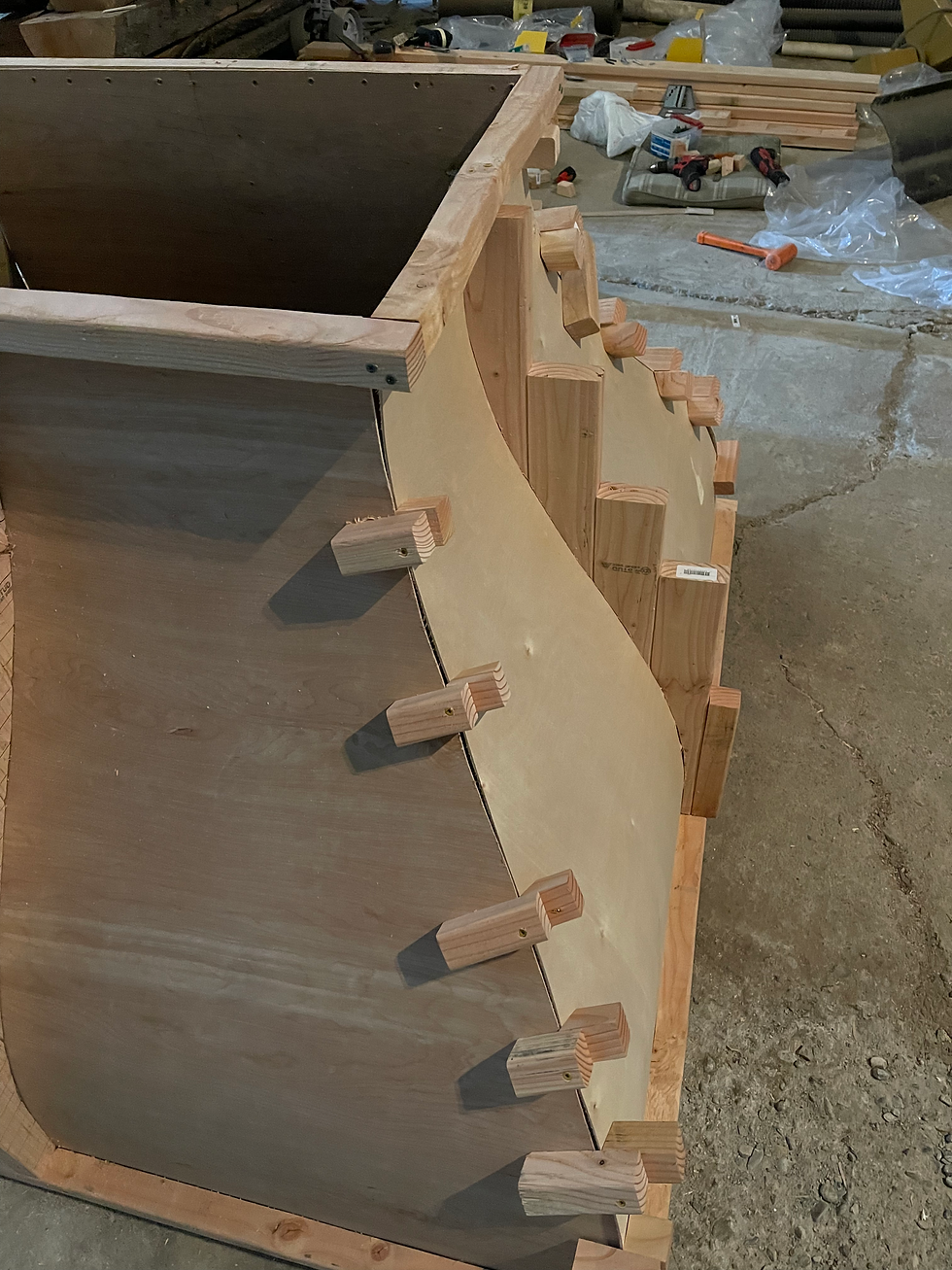
To build the inlet, we graphed the curvature of the supports and then recreated the graph by hand (see photo 3). The supports bend small sheets of wood to the desired curvature.
You can see in photo 6 that the supports don't completely seal the inlet. To fix the problem, we added caulk and tape.


Testing Chamber
Between the inlet and the diffuser is the testing chamber—which was (by far) the easiest piece to assemble. The testing chamber is a rectangular prism with dimensions 1 x 2 x 3 ft (roughly speaking).
Outside the testing chamber is a contraption Daniel built that enables us to measure lift (see photos 3 and 4). When the wing is pushed up, an indicator moves—effectively capturing the measurement of lift the wing experiences.
Results


We obtained an average windspeed reading of about 6 m/s or 13.4 mph (see photos 3 through 5). Although this speed does not seem substantial, it was enough to get data. We were able to generate enough force to lift a wing about an inch (see video).
More importantly, Daniel was accepted by TUM. Last I spoke with him, he was being recruited to apply for a rigorous internship at Porsche.
Congratulations, Daniel. Keep dreaming!